Project: ATX Cube Case
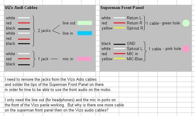


Referring to TOP LEFT image of Vizo - How is the 2 jacks split up - As in which wires go where? Im guessing top 3 to one jack and bottom 3 to other jack??DeanMF wrote: VIZO Audio Cable Image
Which one would be line in and which line out? Please split that jack into a bit more details...
K thx bubye...
My BF2142 Stats:

Slasher : Former member of www.PCFormat.co.za
I have reached the end of my near 5 year forum life. Farewell good days...
slasher (at) webmail (dot) co (dot) za
Slasher : Former member of www.PCFormat.co.za
I have reached the end of my near 5 year forum life. Farewell good days...
slasher (at) webmail (dot) co (dot) za
I guess the first three cables are for the first jack (line out) and the second three to the second jack (line in)Slasher wrote:Referring to TOP LEFT image of Vizo - How is the 2 jacks split up - As in which wires go where? Im guessing top 3 to one jack and bottom 3 to other jack??DeanMF wrote: VIZO Audio Cable Image
Which one would be line in and which line out? Please split that jack into a bit more details...
K thx bubye...

Forum Points: 25 618
ok, i might be wrong, but is the Vizo panel grounded already by something else? or does it need the ground to be connected?
i would have to say for the LINE IN and OUT connectors:
we need to determine what is Power and what isn't, normally RED (and YELLOW) supplies power, therefore:
white - white
red - yellow
black - red
(it's only audio, so if it's not correct, it just won't sound right, then try something else)
for the MIC connectors from the Superman cables, do the same, but exclude the black GND connector from the superman pins:
white - white
red - yellow
black - red
the reason i say RED - YELLOW is that MIC BIAS is definitely for POWER. therefore the superman panel more than likely uses the YELLOW cable to supply power, and the Vizo panel uses RED to supply power...
i'm searching the net, but nothing found yet...
btw - i'm not saying do the above, but it makes the most sense to me so far, until i can find something that is 100% conclusive...
EDIT: oh yeah, i meant to say this yesterday, NICE CASE!!!
as far as i know, No, it is just audio...
i could be wrong though...
think of when you wire speakers wrong in the car, you get feedback, etc. or you just don't get power, the only time something will go wrong is if you short it out, which you can only do if you touch + and - together, which you won't be doing anyhow...
i mailed Vizo, let's see what they say...
i got the manual, it says nothing different than what you stated for the front panel audio header...
let me put it this way - "I" would try it...
if "I" were to try it, i would just put the pins on the connectors and try diff combinations.. but "I" woudl only try the one set until i know for sure..
sorry - if i find anything else, i will definitely let you know...

let me put it this way - "I" would try it...
if "I" were to try it, i would just put the pins on the connectors and try diff combinations.. but "I" woudl only try the one set until i know for sure..
sorry - if i find anything else, i will definitely let you know...
If you decide to try anything I would recommend using a cheap set of R40 odd speakers from Matrix or some crap lying around - dont blow your decent set or even just damage them... You just need to make sure that power is supplied the right way around or it will damage most speakers...
My BF2142 Stats:
Slasher : Former member of www.PCFormat.co.za
I have reached the end of my near 5 year forum life. Farewell good days...
slasher (at) webmail (dot) co (dot) za
Slasher : Former member of www.PCFormat.co.za
I have reached the end of my near 5 year forum life. Farewell good days...
slasher (at) webmail (dot) co (dot) za
i think that is a very good idea...If you decide to try anything I would recommend using a cheap set of R40 odd speakers from Matrix or some crap lying around - dont blow your decent set or even just damage them... You just need to make sure that power is supplied the right way around or it will damage most speakers...
thanks Slasher!!
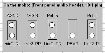
Ok dude, If you have a multi meter with a continuity check then it is easy to get it right. The tip of the microphone jack is where your audio goes out of the MIC. The ring is USUALLY for the bias and the body of the jack is ground. So what you would first need to do is make sure which colour wire is connected to the tip, ring and body of the jack. You would need to connect the body of the jack to your mobo's "AGND" pin (I am assuming the black wire is the ground pin), connect the ring to "MIC2_RR" (Assuming its yellow, also it seems your MoBo has a stereo microphone) and finally connect the tip to MIC2_RL (Assumed red) If you mic does not work move the ring to the VCC3 pin and then know that you don't have a stereo mic.
For the line out, The tip and ring is audio, left and right (I cant remember if the tip is right or left) and the body is ground. Connect the audio wires to LINE2_RR and LINE2_RL, then connect the ground to RET_L and .._R. Test and see if it works. I honestly cant tell you if that will work but just try it.
Precausions: Don't short anything out, especially between the MIC bias and ground and if there is sound being sent through the line out and it is shorted to ground. Actually, that would only be a real problem if the computer has power. So best would be to just switch the PC off while you are working on it... (I can hear everyone go: "WELL DUH!!!"). Anyway good luck.
Nice case again
damn - i knew i should have paid attention to my dad (the electrician/radio mac)...If you have a multi meter with a continuity check then it is easy to get it right
@Dean - let us know... Good Luck!
Last edited by douglash on 22 Aug 2007, 11:58, edited 1 time in total.