Haven't done any electronics work since high school so I'm basically clueless.
What I need is a design to take power from the power connector from a PSU (will use the FDD power connector as it will never get used otherwise) to a switch - preferably one of those switches that works as a rheostat - starts at OFF and works the voltage up - and then from the switch to a strip of LEDs.
This is to power these UV LEDs.
Now, a floppy drive connector has both 5v and 12v - which to use?
These are 5v LEDs, but because the system will be parallel, resistance decreases as more parallel links are joined - therefore the more 5V LEDs I use, the less resistance and thus overvoltage could occur - is that correct? As I said, I'm very rusty...
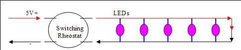
Here is a BASIC design I have done, maybe one of you can verify the correctness or lack thereof?
The idea is to create a PVC or epoxy tube (imagine a straw filled with hard-set resin) which has the electronics inside of it, with just the LEDs sticking out. Should be small and easy to hide away...
Thanks guys.