
LED temp gaugeunfortunately it isn't fantastic and dates from 2003 so no vista support, i'm sure.
i'll have to go find it in the phillips hand book in the UJ library. the one i'm thinking of, uses a theremistor.
Modding electronics
-
RobThePyro
- Registered User
- Posts: 1210
- Joined: 04 Dec 2006, 02:00
- Location: Durbz!
- Contact:
Re: Modding electronics
Hey guys if your looking for compoents and stuff...
http://www.pro-tecc.co.za (Newly launched electronics site, with just about every electronics compoent under the sun avalible, If they dont have it, they can prob get it and with some searching a bunch of usefull stuff like heat shrink
  , Site is still under construction and pics are comming soon....)
Hope thats useful!
Rob~
http://www.pro-tecc.co.za (Newly launched electronics site, with just about every electronics compoent under the sun avalible, If they dont have it, they can prob get it
Hope thats useful!
Rob~

Re: Modding electronics
It is now a sticky
Re: Modding electronics
Greatly appreciated Lance 
Re: Modding electronics
Something simple you might want to use in the future.
Takes 8 - 18 volts and brings it down to 5v
Could be handy for LED's or something.
A while back i wanted to connect my Ps3 to my VGA monitor and tried to build a video sync splitter.
that would split the H and V from the yellow video RCA connector and feed it into the monitor, but i ended up popping the monitor.
But the Voltage regulator works well and is very simple to build.
Just watch out for shorts and don't switch the poles as the transistor get extremely hot and will burn you if you touch it.

Re:
Using Samaya's circuit with the below one.Samaya wrote:Temperature dependant fan controller.
R1 is a 10k OHM NTC (Negative temperature coefficient) Resistor. Its resistance changes as temperature changes. If you have any questions on this just PM me
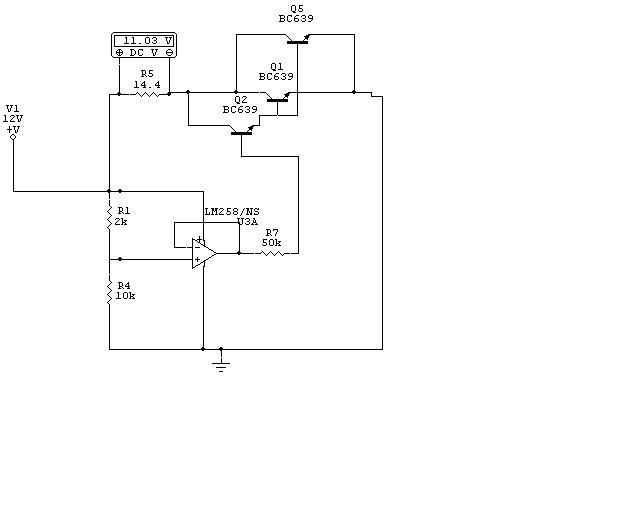

You will end up having a LED level of the fan's spin speed.
The hotter the CPU get the quicker the fan spins cus more voltage is being sent to the fan and connected in parallel with the above volt meter will light up more LED's in level.
Dont mean to bash samaya's circuit, but the circuit is just simple and needs to be tested you might fry your CPU.
Cus if the CPU gets hot the fan will spin but it might not spin quick enough to cool so it will get hotter and hotter and end up spinning the CPU fan at full speed.
Re: Modding electronics
The circuit I made is not actually intended as a CPU fan controller, its more for case fans and the like.
The bashing is fine, You have shown a draw back of the little circuit. I don't completely agree with you about the cooling down part though. IF you set R4 to an appropriate level then you should be able to get a temperature-to-cooling ratio that should be sufficient to cool the CPU down. I use that same circuit to drive my fans in my case and it works fine. I wouldn't suggest using it as a CPU fan controller because if your CPU fries then you are going to blame me and I am going tell you to eat non-recyclable waste... lol.Dont mean to bash samaya's circuit, but the circuit is just simple and needs to be tested you might fry your CPU.
Cus if the CPU gets hot the fan will spin but it might not spin quick enough to cool so it will get hotter and hotter and end up spinning the CPU fan at full speed.
Re: Modding electronics
LOL.
You seem to have designed it your self all credit goes to you. I like the work BTW.
I think you could modify the circuit a bit with some research, and then turn it into a CPU fan controller.
And call it the GREENCircuit and save some power , imagine if the whole world had to use your circuit how much power and trees you will be saving. he he.
Anyway.
Lemme try and give some more constructive drawbacks.
If you can find the correct OHM NTC resistor that in balance with the the heatrange it operates into VS the resistance range in conjunction with a CPU's operating temrature range, I can see it working as a CPU cooler. BTW i think most Dell Business desktops has this.
Especially the GX280 and this is also the cause why we have replaced more than 10 of them with the same problem. I think the resistor fails and spins the CPU fan and make it sound like a vacuum cleaner.
Its bios realises this and wont switch on.
Also
the maximum volts your circuit puts out is 11.3 since its exactly 11.3 i take it its been measured.
I would push the fan slightly over 12.V maybe like 14volts at its maximum range.
Not sure if its possible since a PC Power supply only gives 12V.
You seem to have designed it your self all credit goes to you. I like the work BTW.
I think you could modify the circuit a bit with some research, and then turn it into a CPU fan controller.
And call it the GREENCircuit
Anyway.
Lemme try and give some more constructive drawbacks.
If you can find the correct OHM NTC resistor that in balance with the the heatrange it operates into VS the resistance range in conjunction with a CPU's operating temrature range, I can see it working as a CPU cooler. BTW i think most Dell Business desktops has this.
Especially the GX280 and this is also the cause why we have replaced more than 10 of them with the same problem. I think the resistor fails and spins the CPU fan and make it sound like a vacuum cleaner.
Its bios realises this and wont switch on.
Also
the maximum volts your circuit puts out is 11.3 since its exactly 11.3 i take it its been measured.
I would push the fan slightly over 12.V maybe like 14volts at its maximum range.
Not sure if its possible since a PC Power supply only gives 12V.
-
WiK1d
- Registered User
- Posts: 20732
- Joined: 13 Sep 2004, 02:00
- Location: Cruising the streets of Pretoria
- Contact:
Re: Modding electronics
But doesn't most motherboards already control your CPU Fan Speed according to temperature?

-
Prime
- Registered User
- Posts: 27729
- Joined: 01 Mar 2004, 02:00
- Location: Getting into trouble
- Contact:
Re: Modding electronics
I'm looking at your circuit Samaya but where is the output? 
Re: Modding electronics
Where it shows 11.3V + and -Prime wrote:I'm looking at your circuit Samaya but where is the output?
-
Prime
- Registered User
- Posts: 27729
- Joined: 01 Mar 2004, 02:00
- Location: Getting into trouble
- Contact:
Re: Modding electronics
Oh right, sorry, thought that was the input to the op-amp but on closer inspection, i see the input comes from the same source as the power to the op amp 
Re: Modding electronics
You are 100% correct there. I made it with "cost" in mind. I could go and use a temperature sensor from Analogue devices coupled to a Atmel microcontroller and give that as a better design but on the forum I think there might be 4 people that would be capable of building and programming it. So there wouldn't be any point doing that.I am an Embedded Design EngineerSBSP wrote:LOL.
You seem to have designed it your self all credit goes to you. I like the work BTW.
An NTC resistor, by design, is non-linear. These things are usually specified to be linear over a certain range within a certain percentage. So you would have to know what range your temperature would be in to get the right linear reaction from the NTC for your design.SBSP wrote: If you can find the correct OHM NTC resistor that in balance with the the heatrange it operates into VS the resistance range in conjunction with a CPU's operating temrature range, I can see it working as a CPU cooler. BTW i think most Dell Business desktops has this.
Especially the GX280 and this is also the cause why we have replaced more than 10 of them with the same problem. I think the resistor fails and spins the CPU fan and make it sound like a vacuum cleaner.
Its bios realises this and wont switch on.
No the 14V wont be possible. Also the 11.03V is indicative of the voltage drop across the fan. So you have 11Vdc over the fan. The missing 1V is measured over the transistors and is due, in part, to the biasing of the transistors and mostly the OpAmp. I could change the OpAmp to a rail to rail OpAmp but would then need to put a 5V regulator in there PLUS the transistors will have to be changed as well. SHLEP...SBSP wrote: Also
the maximum volts your circuit puts out is 11.3 since its exactly 11.3 i take it its been measured.
I would push the fan slightly over 12.V maybe like 14volts at its maximum range.
Not sure if its possible since a PC Power supply only gives 12V.
-
-Prometheus-
- Resident Drama Llama
- Posts: 967
- Joined: 05 Mar 2008, 02:00
- Contact:
Re: Modding electronics
........................................................................................................................................................................................................
........................................................................................................................................................................................................
........................................................................................................................................................................................................
........................................................................................................................................................................................................
........................................................................................................................................................................................................
........................................................................................................................................................................................................
........................................................................................................................................................................................................
........................................................................................................................................................................................................
........................................................................................................................................................................................................
........................................................................................................................................................................................................
........................................................................................................................................................................................................
........................................................................................................................................................................................................
........................................................................................................................................................................................................
........................................................................................................................................................................................................
........................................................................................................................................................................................................
........................................................................................................................................................................................................
........................................................................................................................................................................................................
........................................................................................................................................................................................................
........................................................................................................................................................................................................
........................................................................................................................................................................................................
........................................................................................................................................................................................................
........................................................................................................................................................................................................
........................................................................................................................................................................................................
........................................................................................................................................................................................................
........................................................................................................................................................................................................
........................................................................................................................................................................................................
........................................................................................................................................................................................................
........................................................................................................................................................................................................
........................................................................................................................................................................................................
........................................................................................................................................................................................................
........................................................................................................................................................................................................
........................................................................................................................................................................................................
........................................................................................................................................................................................................
........................................................................................................................................................................................................
........................................................................................................................................................................................................
........................................................................................................................................................................................................
........................................................................................................................................................................................................
........................................................................................................................................................................................................
........................................................................................................................................................................................................
........................................................................................................................................................................................................
........................................................................................................................................................................................................
........................................................................................................................................................................................................
........................................................................................................................................................................................................
........................................................................................................................................................................................................
........................................................................................................................................................................................................
........................................................................................................................................................................................................
........................................................................................................................................................................................................
........................................................................................................................................................................................................
........................................................................................................................................................................................................
Last edited by -Prometheus- on 03 Apr 2011, 22:06, edited 1 time in total.
-
Prime
- Registered User
- Posts: 27729
- Joined: 01 Mar 2004, 02:00
- Location: Getting into trouble
- Contact:
Re: Modding electronics
Yes, i would be interested to learn.-Prometheus- wrote:Always find it funny that people will use vero board when making pcbs is actually quite easy. The stuff I would recommend is Positiv 20 or a pre-coated board. If you use Positiv 20 spray it into a dark bottle and dilute 1:1 with acetone. It will discolor but the acetone won't destroy it right away. The thinner you can spread this the better and it's just too viscous to spread evenly in its original dilution. The most critical part is the exposure. The board should be protected from all light prior to exposure and exposure should be done with the positive completely against the board.Prime wrote:
I've done my own print outs but i haven't gotten to the etching stage as i haven't succeeded in getting a good image transfer onto the board. i bought some transfer sheet from communica to try. and i'll maybe do that this weekend. any one done etching with HCL? is there a reason they use ferric chloride?
HCL (mixed with some other stuff actually) is supposed to give more professional results but is harder to work with and degrades more quickly. Ferric chloride actually works good even when you don't heat it, just don't spill it, on anything. Perhaps I should make a tutorial how to do this.
Vero boards are nice for a prototype but are very limited.
Don't you need special boards for photo etching?
Re: Modding electronics
The tutorial is a good idea. I haven't done my own etching in a VERY long time...-Prometheus- wrote: HCL (mixed with some other stuff actually) is supposed to give more professional results but is harder to work with and degrades more quickly. Ferric chloride actually works good even when you don't heat it, just don't spill it, on anything. Perhaps I should make a tutorial how to do this.
Re: Modding electronics
Designing a Pcb for my Fan Controller is next.I draw the circuit diagram and do the pcb layout on Eagle Cad.I use the program's Cam output to plot the pcb image straight onto the copper-clad board.This is done on my X-Y plotter using a modified pen with waterproof permanent ink.The pcb is then etched using ferric chloride in a bubble etch tank.
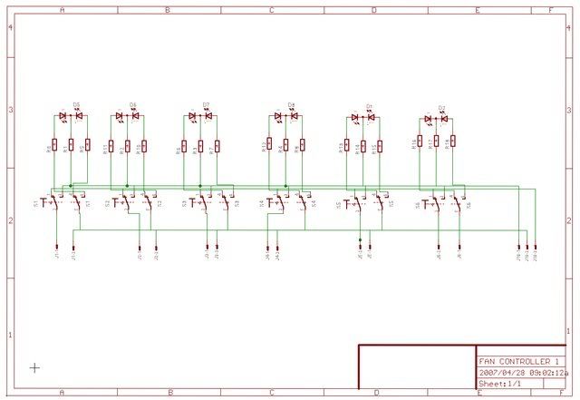
I use the program's Cam output to plot the pcb image straight onto the copper-clad board.This is done on my X-Y plotter using a modified pen with waterproof permanent ink.It is a standard 0.5mm waterproof permanent marker.What I do is take a piece of pcb to the shop draw lines with various pens ,wait a few seconds ,wet my finger and try to rub them out the one that survives the best is the one i buy - a dozen 0r 2 cheaper than their socalled expensive fat tipped etch resistant pens.
I then disect a disposible felt tip plotter pen and mount the the marker into it, setting the tip hieght to allow for the pc board thickness.Not rocket science but it works.
I use this method for prototypes,simple boards and small quantities if I have a large demand is let the pro,s do it.
Pen setup.


My etch tank is a simple bubble etch tank.The tank is a household plastic container with lid .Iinside I epoxied a deviice which is used for airing fish tanks ,whick is linked with pcv pipe to a fish tank air pump.The tank is placed in another large plastic container which I fill with hot water to heat the Ferric Cloride(Etchant).If you use ferric cloride, beware it is extremely corrosive and stains clolhes.Use only NO METAL AROUND IT.


Plotter.


Some "Power Bus and Led Strips and some combo,s made this way

I use the program's Cam output to plot the pcb image straight onto the copper-clad board.This is done on my X-Y plotter using a modified pen with waterproof permanent ink.It is a standard 0.5mm waterproof permanent marker.What I do is take a piece of pcb to the shop draw lines with various pens ,wait a few seconds ,wet my finger and try to rub them out the one that survives the best is the one i buy - a dozen 0r 2 cheaper than their socalled expensive fat tipped etch resistant pens.
I then disect a disposible felt tip plotter pen and mount the the marker into it, setting the tip hieght to allow for the pc board thickness.Not rocket science but it works.
I use this method for prototypes,simple boards and small quantities if I have a large demand is let the pro,s do it.
Pen setup.
My etch tank is a simple bubble etch tank.The tank is a household plastic container with lid .Iinside I epoxied a deviice which is used for airing fish tanks ,whick is linked with pcv pipe to a fish tank air pump.The tank is placed in another large plastic container which I fill with hot water to heat the Ferric Cloride(Etchant).If you use ferric cloride, beware it is extremely corrosive and stains clolhes.Use only NO METAL AROUND IT.
Plotter.
Some "Power Bus and Led Strips and some combo,s made this way
Re: Modding electronics
Designing a Pcb for my Fan Controller is next.I draw the circuit diagram and do the pcb layout on Eagle Cad.I use the program's Cam output to plot the pcb image straight onto the copper-clad board.This is done on my X-Y plotter using a modified pen with waterproof permanent ink.The pcb is then etched using ferric chloride in a bubble etch tank.
I use the program's Cam output to plot the pcb image straight onto the copper-clad board.This is done on my X-Y plotter using a modified pen with waterproof permanent ink.It is a standard 0.5mm waterproof permanent marker.What I do is take a piece of pcb to the shop draw lines with various pens ,wait a few seconds ,wet my finger and try to rub them out the one that survives the best is the one i buy - a dozen 0r 2 cheaper than their socalled expensive fat tipped etch resistant pens.
I then disect a disposible felt tip plotter pen and mount the the marker into it, setting the tip hieght to allow for the pc board thickness.Not rocket science but it works.
I use this method for prototypes,simple boards and small quantities if I have a large demand is let the pro,s do it.
Pen setup.
My etch tank is a simple bubble etch tank.The tank is a household plastic container with lid .Iinside I epoxied a deviice which is used for airing fish tanks ,whick is linked with pcv pipe to a fish tank air pump.The tank is placed in another large plastic container which I fill with hot water to heat the Ferric Cloride(Etchant).If you use ferric cloride, beware it is extremely corrosive and stains clolhes.Use only NO METAL AROUND IT.
Plotter.
Some "Power Bus and Led Strips and some combo,s made this way
Re: Modding electronics
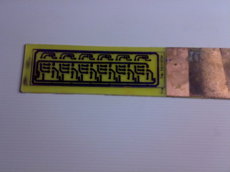
This is how I make PCB'S at home.
I draw the circuit diagram and do the pcb layout on Eagle Cad.I use the program's Cam output to plot the pcb image straight onto the copper-clad board.This is done on my X-Y plotter using a modified pen with waterproof permanent ink.The pcb is then etched using ferric chloride in a bubble etch tank.
I use the program's Cam output to plot the pcb image straight onto the copper-clad board.This is done on my X-Y plotter using a modified pen with waterproof permanent ink.It is a standard 0.5mm waterproof permanent marker.What I do is take a piece of pcb to the shop draw lines with various pens ,wait a few seconds ,wet my finger and try to rub them out the one that survives the best is the one i buy - a dozen 0r 2 cheaper than their socalled expensive fat tipped etch resistant pens.
I then disect a disposible felt tip plotter pen and mount the the marker into it, setting the tip hieght to allow for the pc board thickness.Not rocket science but it works.
I use this method for prototypes,simple boards and small quantities if I have a large demand I let the pro,s do it.
Pen setup.
My etch tank is a simple bubble etch tank.The tank is a household plastic container with lid .Iinside I epoxied a deviice which is used for airing fish tanks ,whick is linked with pcv pipe to a fish tank air pump.The tank is placed in another large plastic container which I fill with hot water to heat the Ferric Cloride(Etchant).If you use ferric cloride, beware it is extremely corrosive and stains clothes.
Plotter.
Some "Power Bus and Led Strips and some combo,s made this way
Re: Modding electronics
That is awesome!!! Brilliant for small projects like you said. Nice write up too.
For those of you wanting to try this, Ferric Chloride can be bought at most decent electronics shop's (not your tv repair mans shop though). And its not that overly expensive either. You will probably find the raw PCB's there as well. The X-Y plotter is awesome but if you really can't find anything similar then you could do it by hand, which will be time consuming and you might make a couple of mistakes so make a design on paper first.
For those of you wanting to try this, Ferric Chloride can be bought at most decent electronics shop's (not your tv repair mans shop though). And its not that overly expensive either. You will probably find the raw PCB's there as well. The X-Y plotter is awesome but if you really can't find anything similar then you could do it by hand, which will be time consuming and you might make a couple of mistakes so make a design on paper first.
-
Prime
- Registered User
- Posts: 27729
- Joined: 01 Mar 2004, 02:00
- Location: Getting into trouble
- Contact:
Re: Modding electronics
Nice.
Damn, i missed a plotter that was being thrown out a few days ago. It was probably broken but still
Damn, i missed a plotter that was being thrown out a few days ago. It was probably broken but still
-
Prime
- Registered User
- Posts: 27729
- Joined: 01 Mar 2004, 02:00
- Location: Getting into trouble
- Contact:
Re: Modding electronics
Ok, please edit your posts. you posted the tut 4 times.
Re: Modding electronics
Sorry, keyboard gremlins.
Thanx
Thanx
-
Prime
- Registered User
- Posts: 27729
- Joined: 01 Mar 2004, 02:00
- Location: Getting into trouble
- Contact:
Re: Modding electronics
LOL NP.rm5d wrote:Sorry, keyboard gremlins.
Thanx
Any idea what plotters cost and who sells them. sorry, i know its a little of topic