Page 3 of 4
Re: Modding electronics
Posted: 17 Jan 2009, 13:04
by UrBaN
Can I be a pest and ask one of the electronics peeps to do a design for me?
Haven't done any electronics work since high school so I'm basically clueless.
What I need is a design to take power from the power connector from a PSU (will use the FDD power connector as it will never get used otherwise) to a switch - preferably one of those switches that works as a rheostat - starts at OFF and works the voltage up - and then from the switch to a strip of LEDs.
This is to power
these UV LEDs.
Now, a floppy drive connector has both 5v and 12v - which to use?
These are 5v LEDs, but because the system will be parallel, resistance decreases as more parallel links are joined - therefore the more 5V LEDs I use, the less resistance and thus overvoltage could occur - is that correct? As I said, I'm very rusty...
Here is a BASIC design I have done, maybe one of you can verify the correctness or lack thereof?
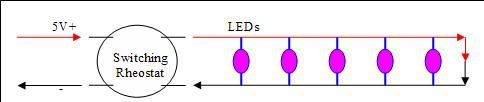
The idea is to create a PVC or epoxy tube (imagine a straw filled with hard-set resin) which has the electronics inside of it, with just the LEDs sticking out. Should be small and easy to hide away...
Thanks guys.
Re: Modding electronics
Posted: 17 Jan 2009, 15:29
by Prime
Um, i'll make you a design. it will give me an excuse to play with circuit board etching

Re: Modding electronics
Posted: 17 Jan 2009, 16:26
by Prime
Are you using the spec of LED in the other thread?
Leds in parallel so current ads, resistance drops. at 35mW an LED, thats 175 mW of current max, so you need an 8 ohm resistor?
Someone check my calcs?

Re: Modding electronics
Posted: 20 Feb 2009, 12:26
by SBSP
I stumbled onto this and thought of you guy's always modding something.
How to create a PCB with the toner transfer method (Normal Laser Printer)
http://www.wonderhowto.com/how-to/video ... od-237547/
Watch the bandwidth
Re: Modding electronics
Posted: 13 May 2009, 09:54
by Prime
Any body got a circuit and suggested software to use switches to control software via usb? I'm thinking up a mod for the media pc i have planned.
Re: Modding electronics
Posted: 13 May 2009, 10:57
by GrimStoner
Check out
http://www.microchip.com/stellent/idcpl ... m=en534494.
It's not easy. You'll have to use something like the PIC18F and program it. It's not like parallel where you enable a pin and it outputs 5V.
Re: Modding electronics
Posted: 13 May 2009, 11:00
by GrimStoner
Re: Modding electronics
Posted: 13 May 2009, 13:10
by Prime
i would prefer to avoid PIC's until next year or the year after that when we learn them at varsity. The kits to program them are expensive.
i am basically looking for a logic circuit that detects a high input and sends a signal to the computer which responds appropriately. My knowledge of programming is limited to delphi 7 and c. Hence, an off the shelf piece of software would be fantastic.
will check out that other link.
Re: Modding electronics
Posted: 13 May 2009, 14:25
by GrimStoner
What about stripping a usb mouse, and only keep the button? Just dunno how you'd capture the click event for that specific mouse... Hmm...
Re: Modding electronics
Posted: 13 May 2009, 17:31
by Samaya
Go look at these guys
http://www.ftdichip.com
They sell a IC that converts the USB into RS232 or parallel port.
OR
You could buy a USB to serial converter device, strip off its housing and use the insides for your project... (use it like you would a serial port)
Re: Modding electronics
Posted: 01 Jul 2009, 10:07
by Prime
Re: Modding electronics
Posted: 08 Jul 2009, 16:06
by Samaya
Thats a cool link.
This
LINK is just as handy, especially if you know just enough about RF too cause groot k#k, like me...
Re: Modding electronics
Posted: 03 Oct 2009, 22:33
by Prime
So I etched my first circuit board today.
Take glossy Paper (such as a magazine page) and print your design onto it.
Place design facedown onto cleaned and polished copper.
cover over with baking paper.
Set you clothes iron to farking hot and iron it. takes about 5 minutes. be sure to apply force and press it thoroughly all over.
Use tweezers and check a small edge.
If the toner has transferred properly, remove the paper carefully as it will be hospital grade hot. Allow to cool and immerse in Ferric chloride.

Then you just need a really fine drill bit for the holes.
Things to note:
use a laser jet for the print. High gloss photo paper also works apparently.
Wear gloves. Taking one for the team is not cool! and ferric chloride is nasty stuff.
Have a container of bicarb and water handy in case you have an accidents.
Re: Modding electronics
Posted: 09 Oct 2009, 15:56
by Samaya
Nice one. I'd like to see a picture of that board.
I had to fix my fan controller the other day. The 2 x BC639 transistors I were using stopped. So I replaced them with a BSP250 Mosfet. I also changed the circuit a bit to work from lower voltages. I'll put the circuit up over the weekend.
Re: Modding electronics
Posted: 28 Oct 2009, 10:01
by Prime
http://www.mantech.co.za/Technical/Atta ... -FACTS.PDF
interesting reading, not highly technical but informative

Right, let me go find some pics of the boards i have made. don't have any pre etch photo's though
Re: Modding electronics
Posted: 28 Oct 2009, 10:18
by Prime
Samaya wrote:Nice one. I'd like to see a picture of that board.
I had to fix my fan controller the other day. The 2 x BC639 transistors I were using stopped. So I replaced them with a BSP250 Mosfet. I also changed the circuit a bit to work from lower voltages. I'll put the circuit up over the weekend.
I have started using TIP package transistors for everything that needs to handle current. stocked up on tip 31C and 32C as well as TIP 41C and 42C transistors.
what is the gate voltage required on those Mosfets?
Re: Modding electronics
Posted: 28 Oct 2009, 13:15
by Samaya
The gate voltage is about -20Vdc with a threshold of -2.8V. Current at 3A. So I think its just the right thing to use.
And I forgot to upload the diagram (and its NOT very complicated)
Re: Modding electronics
Posted: 28 Oct 2009, 14:15
by doo_much
Do you guys know anything about thermocouples?
I need something that'll switch on a fan at a given temperature and of again at another. Any ideas?
Re: Modding electronics
Posted: 28 Oct 2009, 15:04
by Prime
doo_much wrote:Do you guys know anything about thermocouples?
I need something that'll switch on a fan at a given temperature and of again at another. Any ideas?
http://www.national.com/ds/LM/LM35.pdf
You want it to turn a fan on for a range? Assuming its to cool something, then I assume you don't mind if it does not switch the fan off for any value above a certain temperature.
If so you will need to set up a transistor or Mosfet to trigger for that particular of current or voltage respectively.
Re: Modding electronics
Posted: 28 Oct 2009, 15:25
by doo_much
Thanks, I'll have a look.
Re: Modding electronics
Posted: 28 Oct 2009, 16:14
by Prime
Just also check that whatever choice of LM35 you use can handle the thermal power. You might need a T220 or "Tin can" package.
Re: Modding electronics
Posted: 28 Oct 2009, 16:33
by Prime
http://www.mantech.co.za/Stock.aspx?Query=LM35and
- Spoiler (show)
- I will be building some LM35 circuits for my mod, one of these days
Re: Modding electronics
Posted: 28 Oct 2009, 22:27
by Samaya
You can also use a thermistor (temperature resistor) in either NTC(negative temperature coeficient) or PTC (positive temperature coeficient) With a PTC your resistance increases as temperature does, and NTC it decreases as temp increases. Then you can just something like my fan controller somewhere in here and you get exactly what you require.
Re: Modding electronics
Posted: 29 Oct 2009, 09:22
by Prime
http://www.national.com/ds/LM/LM350.pdf?
I am building a regulated power supply using LM350's. it will have +12 and -12 Volt output. Does anyone know anything about solidstate current protection. my Transformers and their filter circuitry are only rated at 1.75 A each.
I want to build in over current protecion for anything above 1.5A with an LED that comes on rather than a fuse

Re: Modding electronics
Posted: 29 Oct 2009, 12:21
by Samaya
You can limit it with shunt protection. You would have a 0.466Ohm resistor in series with your supply line to your load. Connect a PNP BJT over that, the collector before the resistor and the base after the resistor. As soon as the voltage across the resistor increases to more than 0.7V it starts conducting. You can then have a resistor again on the emittor to ground that then will have a voltage drop across that and you can use the voltage drop to turn your main BJT/FET on or off depending on your arrangement. Let me know if you need help.