Page 11 of 12
Posted: 02 Oct 2007, 18:18
by Samaya
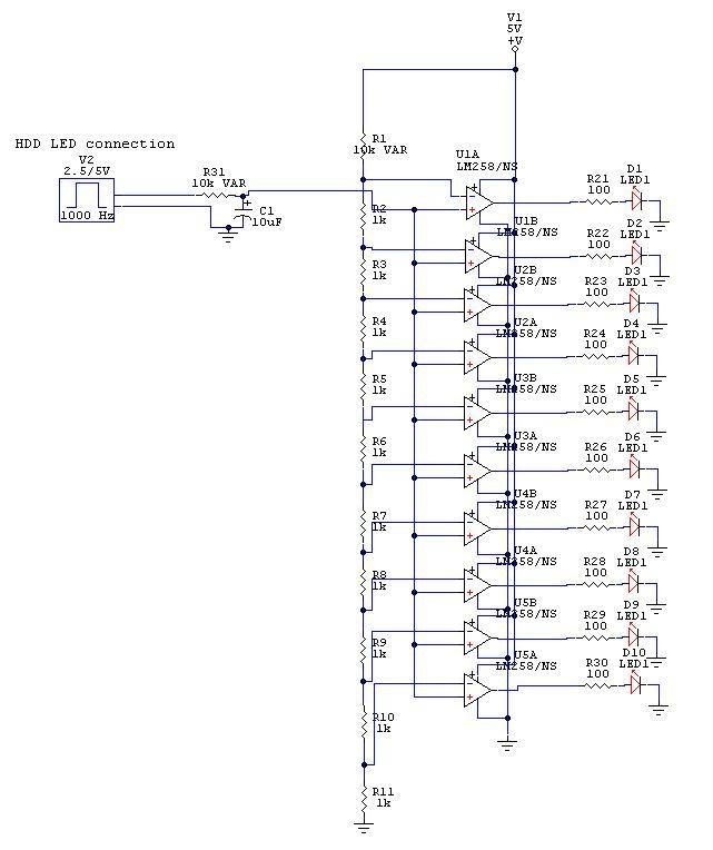
As requested by LJ. Here is the circuit of the fan driver / controller
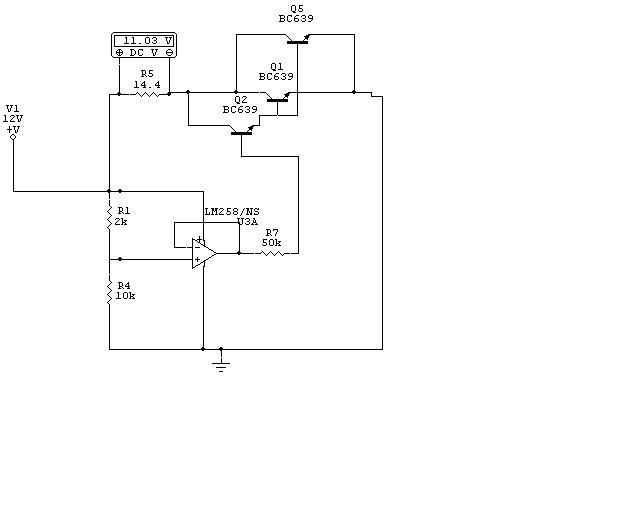
If you have questions, post them here.
Posted: 02 Oct 2007, 18:22
by Lithe_Joint
Thanks Dude! I'm gonn go and burn my fingers a bit later

Posted: 02 Oct 2007, 18:34
by RobThePyro
Samaya wrote:So you could in fact make a bar graph temperature display with it as well.
I could be wrong but couldnt you just use an LM3914 or 2? would assume that would be easyer... lol like this kinda
http://www.zen.pqsound.co.za/index.php? ... cts_id=245
just my 1.3 cents....
Rob~!
Posted: 02 Oct 2007, 20:29
by Samaya
RobThePyro wrote:Samaya wrote:So you could in fact make a bar graph temperature display with it as well.
I could be wrong but couldnt you just use an LM3914 or 2? would assume that would be easyer... lol like this kinda
http://www.zen.pqsound.co.za/index.php? ... cts_id=245
just my 1.3 cents....
Rob~!
You could buy this for R145 if you want but whats the fun in that? PLUS this design shouldn't cost you more than say R50 if you buy expensive components

edit: Oh now I remember where that site comes from... LOL
ps: I just looked at the LM3914 and yes it would be easier to use but that
is for lazy engineers LOL (Just kidding)
Posted: 02 Oct 2007, 20:45
by Samaya
Lithe_Joint wrote:Thanks Dude! I'm gonn go and burn my fingers a bit later
Dude I forgot to change R1 to show that it is the 10k OHM NTC resistor. It says 2k because I was busy making sure that the voltages would change. So just remember R1 = 10k NTC Thermistor
Posted: 02 Oct 2007, 21:36
by RobThePyro
LOL.... yea that bar graph thingy is my granfathers design, with 2 lm3914's for sensing audio signals, but a a single lm3914 would be cheap and easy to impliment
Rob~!
Posted: 04 Oct 2007, 15:02
by Lithe_Joint
Samaya wrote:Lithe_Joint wrote:Thanks Dude! I'm gonn go and burn my fingers a bit later
Dude I forgot to change R1 to show that it is the 10k OHM NTC resistor. It says 2k because I was busy making sure that the voltages would change. So just remember R1 = 10k NTC Thermistor
Gotcha.
Posted: 07 Oct 2007, 18:00
by Samaya
I have made some more stuff this weekend.
I have almost finished the activity meter. There are just some small adjustments I need to make for it to work nicely but I have tested and it does work but only a limited margin. I'll fix it sometime during the week or next weekend.
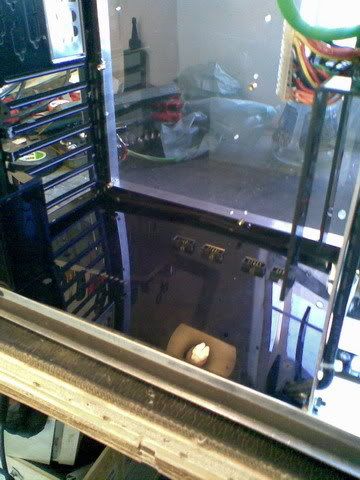
I had to find somewhere to place the actual indicators (leds) So decided to make a cover for the bottom of the case. I then had a bright idea to actually use connectors to get the front panel and USB's connected.
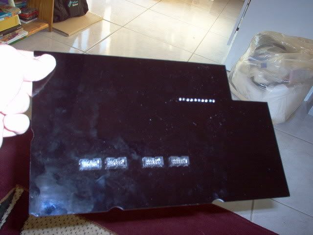
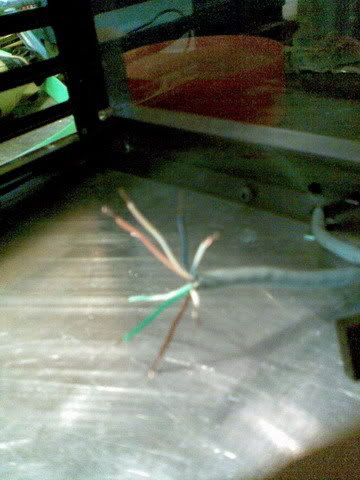
You can see the ten LED leads sticking out on the right.
So for this to fit I will need to redrill some holes for some of the wiring. Which in turn means I have to remove the MoBo and drives. Not to much of a slep cause my case opens up so easily

Posted: 20 Oct 2007, 19:41
by Samaya
I made some changes to my mod these last couple of days. I had LOTS of time you see cause I am between jobs at the moment... (Starting fresh on Monday
)
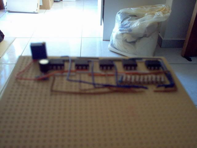
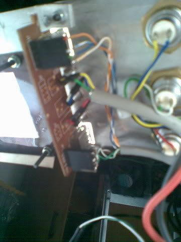
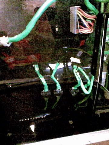
So I decided to take this - specifically the wiring -
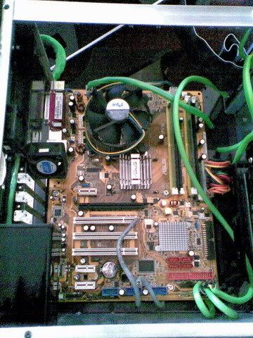
and fix it. The wires were stressing my board and we cant have that.
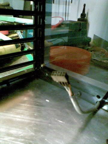
I fit some connectors to the ends of the wires to be plugged into the bottom of the panel.
I also finished the activity meter but still need test it. Will do that later tomorrow. It sits on the bottom of the panel.
And because I had a lot of time, I cleaned up the front panel wiring a bit. I added some nice LED holders aswell.
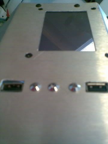
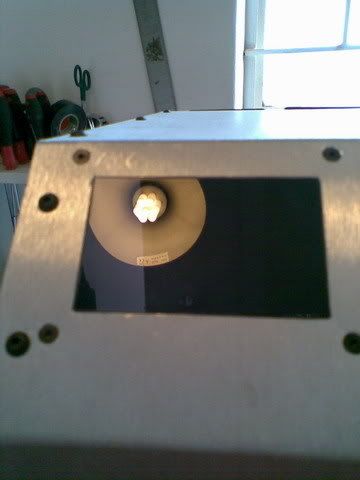
I also remade the LCD cover. The previous one didn't fit very nicely.
I'll do some more modding tomorrow. I still need to test the activity meter, connect up my LCD display and make sure this front panel is connected properly to my MoBo.
Posted: 21 Oct 2007, 20:15
by Samaya
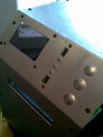
This is where I stopped yesterday. I had to fit the bottom panel and hook it up.
Bottom panel fitted
Made the wires and plugged them in
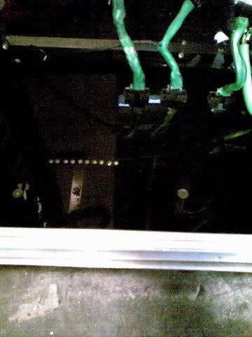
I didn't have time to test the activity meter but that will eventually happen anyway.
Posted: 21 Oct 2007, 21:40
by DAE_JA_VOO
Awesome work man
Wish i had electronics skills like that

Posted: 22 Oct 2007, 13:45
by Samaya
Thanks man
Posted: 22 Oct 2007, 13:53
by DarkRanger
well done dude!!

looks good and neat!
Posted: 22 Oct 2007, 14:32
by Samaya
Sorry about the poor quality pics. I have to use my phone at the moment. I'll ask my photography student cousin to come and take pictures of it when I am satisfied with it. (I can't, however, say when that will be...)
Posted: 27 Oct 2007, 21:47
by Samaya
My activity meter is done and I have to brag, IT LOOKS FRIGGIN AWESOME!!!!
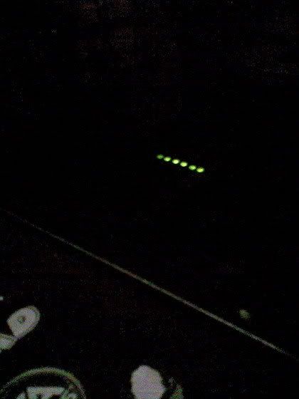
In action
HERE
So what do you think. Oh and thanks OTC
Posted: 27 Oct 2007, 21:50
by DAE_JA_VOO
OMW that's SOOOOO cool!
I hope you know that you're gonna make me one of those for my next mod

Posted: 28 Oct 2007, 00:23
by DoOb
That is soooooo mental Samaya, i so want one aswell, will hav to get rob to make me one
Posted: 28 Oct 2007, 09:08
by RobThePyro
OMG SamayaDude thats just AWSOME!. how did you do it? iv been trying to figure out how to do that for ages!?!?! thats just fracking amazing dude
WELL DONE!
Rob~!
Posted: 28 Oct 2007, 13:27
by Samaya
Posted: 28 Oct 2007, 13:46
by RobThePyro
W00T!!!!!
You do know i can make PCB's Samaya!, Who wants to buy a kit?!?!!?
lol
rob~1
Posted: 28 Oct 2007, 14:38
by Samaya
You sell them...
The worst thing about this meter is that after I built it, RobthePyro showed me a device (lm3914)that does all this in one go. Except for the input ofcourse which makes all the difference.
What you need:
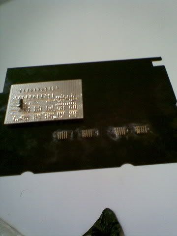
1) Vero board. This is the stuff I built the whole circuit with. Communica sells this in single sheets. Their about +-R20 each.
2) Resistros. You will need 100Ohm per LED(depending on the current drawn per LED) , 1000Ohm (1kilo Ohm) also as many as you have LEDS. Then you will need 1 x 10kOhm Variable resistor and 1 x 100kOhm Variable resistor.
3) Your LEDS. I used 3mm Green LEDs that use 15mA each. So I was safe driving them directly from my Op-amps. If you use the same circuit as I did but with LED’s that need more current, you will need to add Transistors.
4) Op-Amps. I used LM258 dual op-amps. 5 of them will give you 10 usable Op-amps. Be careful with these and do not short them. They are not that friendly. OR you could replace all the op-amps with a lm3914.
5) Optional transistors. You can use BC639-25 transistors if you want to drive up to about 100mA LEDs but then do not go over 5V per transistor. If you require more info just PM me.
To build:
1) There isn’t really a recipe to build this but just make sure you do not have any shorts on the board. THAT is why you need the multimeter. On your meter there needs to be a continuity test (the setting which beeps when you touch your probes together)
2) You will need to know which wire goes to which pin. You will need the circuit for that and the following: Pin 1 – Output A
Pin2 – Inverting Input A (-)
Pin 3 – Non-inverting input A (+)
Pin 4 – Ground
Pin 5 – Non-inverting input B (+)
Pin 6 – Inverting Input B (-)
Pin 7 – Output B
Pin 8 – Vcc
3) After you build this PLEASE test for shorts again. You might think you are the shiz but really even I still make this stupid mistake. Overlooking something is easy when you work with Vero board.
Posted: 28 Oct 2007, 15:06
by WiK1d
http://www.bit-tech.net/modding/2002/06 ... ty_meter/1
There's another one
If you want me to remove it just say the word
Posted: 28 Oct 2007, 15:45
by RobThePyro
OH~! lol i thought it was a cpu activity meter. lol. yes im blind, i was wondering how that works! Wow im surprised the Hdd meter is PWM i though it was allways just on/off...
*Orders lm3914 from dad
*
Thanks
Samaya!!!! Woot
Rob~!
Posted: 28 Oct 2007, 15:57
by Samaya
That is actually a better circuit in that it uses the LM3914 IC. BUT half of the other stuff is not needed as it is not necessary. The opto-coupler and extra Opamps are not necessary. Your MoBo CAN drive an LED anyway so you have a bit of power to play with. So you could really just stick a high'ish resistor with a capacitor in there and you would have a frequency to voltage converter. No need to go complex here.
Posted: 28 Oct 2007, 16:02
by Samaya
RobThePyro wrote:OH~! lol i thought it was a cpu activity meter. lol. yes im blind, i was wondering how that works! Wow im surprised the Hdd meter is PWM i though it was allways just on/off...
*Orders lm3914 from dad
*
Thanks
Samaya!!!! Woot
Rob~!
All that you would need to do is put a 10kOhm variable in line with the LM3914 signal input and a 10uF cap to ground from the signal line. What happens is the capcitor "rectifies" the incoming voltage and literally creates a varying DC voltage with regards to the frequency. So the more the LED is on, the higher the comparing voltage will be.