Page 10 of 12
Posted: 20 Apr 2007, 10:17
by DoOb
DAE_JA_VOO wrote:Yeah

Dude i'm gonna make sure i have NO projects running when i have my first kid. If my kid wants attention, i wanna be able to give him/her attention, just like you're doing.
I just dont want any projects because i'll be like this:
*baby cries*
Me: Hmmmm.... *thinks to myself "modding or baby... hmmm*
*carries on modding*

(i hope HHB doesn't read this thread

)
I DAE I 2nd that bru. And You HOPE You Hope HHB doesnt hey she have you for this.
Samaya, your technics are unique they rock from here to Mozambique. Doing a very good job with this.
Posted: 22 Apr 2007, 19:57
by Samaya
I did some modding this weekend. Mostly doing wiring and some drilling.
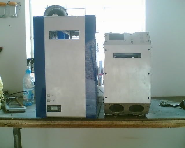
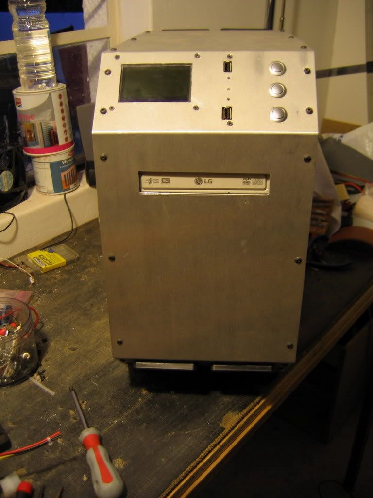
I thought I would just show you a comparison of my previous mod and this one. The one on the left is called "Behemoth", my first mod
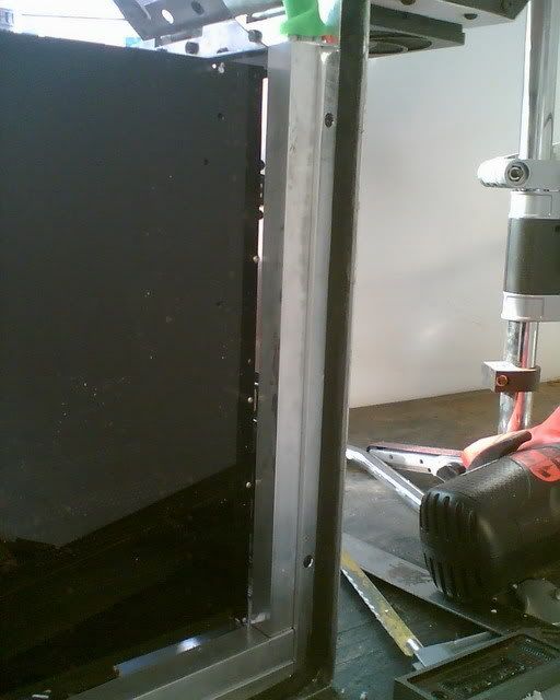
I also made a aluminium cover for the front panel wires
And then I started the wiring
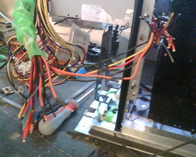
Wires soldered and heat shrinked
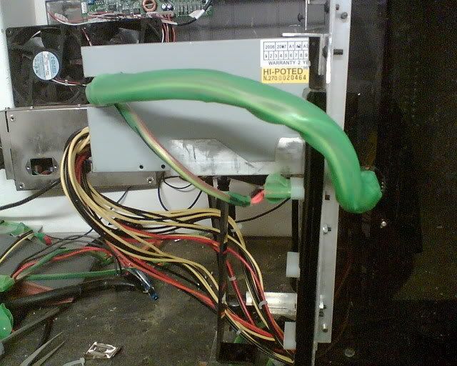
What it looks like when the case is closed
I am nearly done with this mod and I am aiming to be finished by the end of May.
Posted: 23 Apr 2007, 06:27
by Off-The-Chart
man I wish I knew electronics... I think it could make modding so much more enjoyable in doing all that techy stuff yourself...
doing a gr8 job on this one Sam... planning on doing any coloring to the covers at all?
Posted: 29 Apr 2007, 17:47
by Samaya
I did some modding today and I made a single part. I think of all the things I have made for this mod so far this one is my favourite.
I kind of finished all the wiring for the front panel, only thing is I still need to do a couple other things in that area but that will be another update some other time
Anyway here is the part I made
Another view (nice and shiny)
Let me know what you think
Posted: 29 Apr 2007, 23:49
by DAE_JA_VOO
Very cool
Posted: 30 Apr 2007, 22:04
by Samaya
Thanks man
Posted: 01 May 2007, 19:46
by Samaya
As you probably saw in the title, this will be the absolute final update on this mod. The mod is nearly done and therefore won't be updated again. All I still have to do on this mod is connect the front panel USB's, buttons and LEDs. Oh and I also need to clean the insides and do some final polishing. The front panel/ Fan controller will be installed in about a month maybe 2.
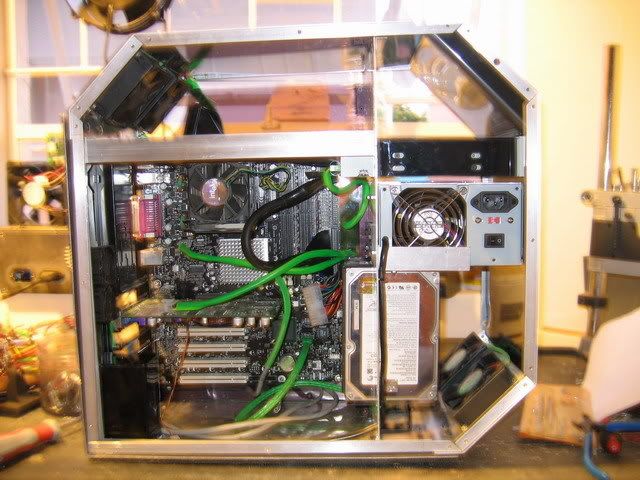
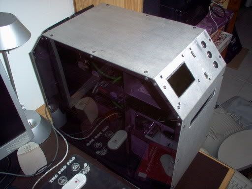
So this is it for Supanaut. I left the side panels off on purpose to get the nice pictures for you guys and girls. I also used a proper camera this time and not my camera phone (which is crap!!!)
On with the show...
The motherboard will be replaced by one that works. Thats why the 24pin connector is not connected. I am going to order a green IDE cable for the DVD writer. Everything is aligned and connected otherwise.
Normal side view
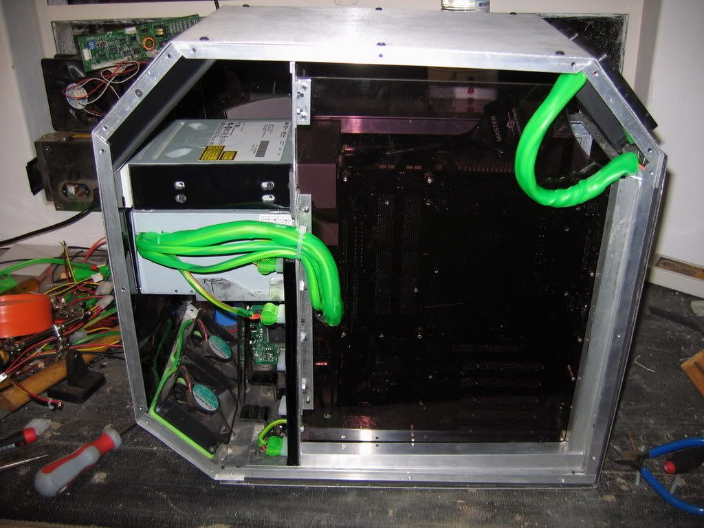
The other side
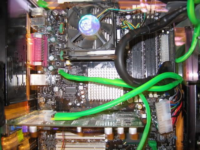
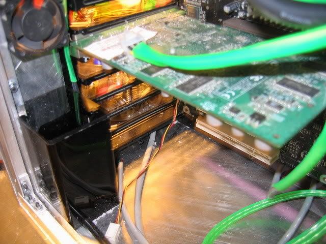
a Closer look at the wiring
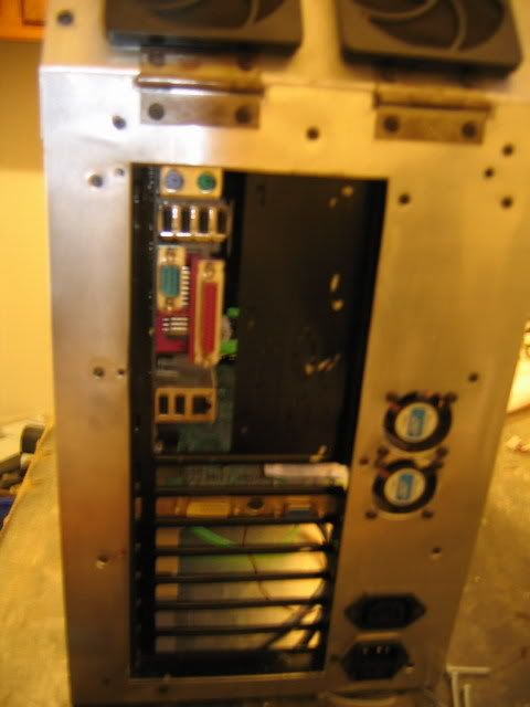
The back
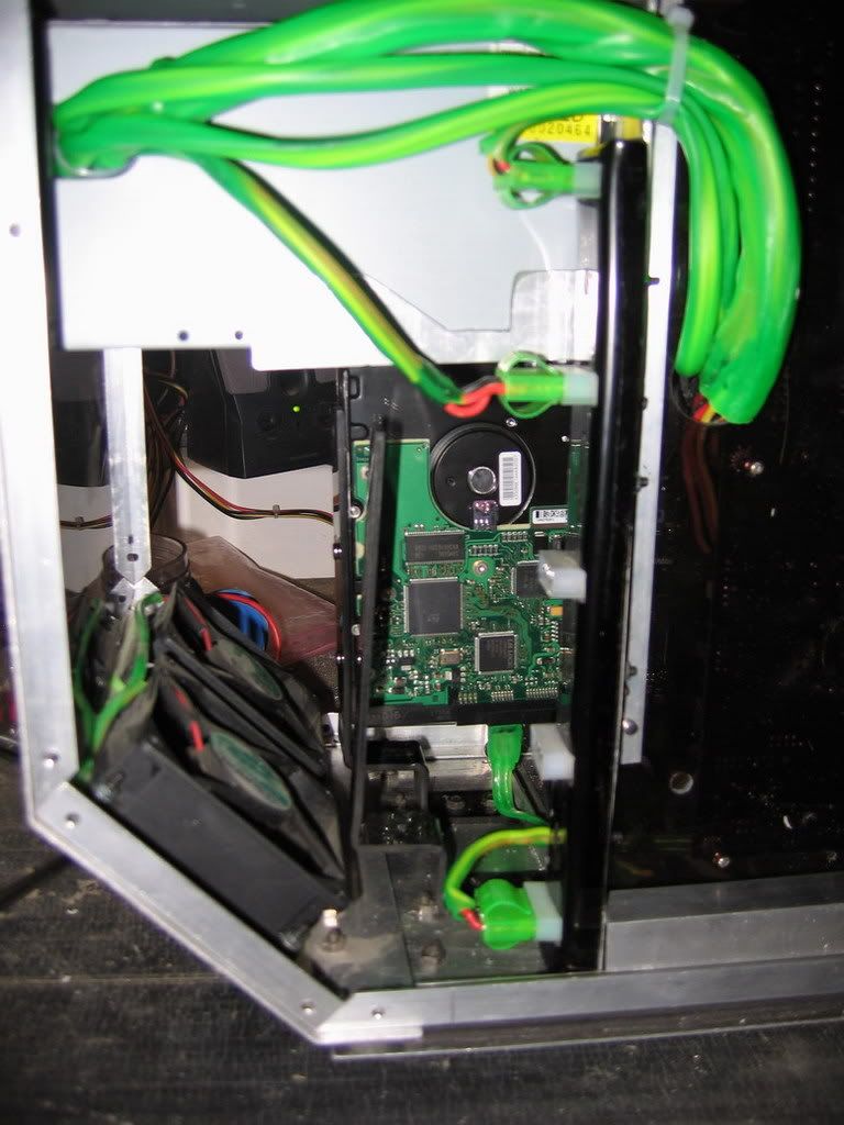
Some insides
The front
:bigups: :bigups: :bigups: :bigups: :bigups:
I hope you enjoyed this project as much as I have enjoyed making it. I don't have any new mods planned for the near future, so you won't see much of me either. I am not going to post anymore pictures of Supanaut as it is basically done. So cheers for now
Posted: 01 May 2007, 19:51
by DAE_JA_VOO
Aah wonderful mod Samaya
I waited and waited for it to be over, but now that it is, i feel

Great work man, great great work
Posted: 01 May 2007, 19:54
by WiK1d
DAE_JA_VOO wrote:I waited and waited for it to be over, but now that it is, i feel
I had the exact feeling now, I was like, what, no
that's just not possible.
Samaya, your work has been exellent
Well done on completing your mod. I think I should start working on mine again.
Posted: 01 May 2007, 19:57
by Samaya
Thanks. When I have finished the cleaning and all the other small things, I will send the 2 of you the final pics.
Posted: 01 May 2007, 19:59
by DAE_JA_VOO
w00tage
We get final pics
Posted: 03 Sep 2007, 12:58
by Samaya
I have to say something. I was wrong in saying that there will never be another update to this mod. I of all people should know that a MOD is never 100% completely done.
But there is a promise I made and I will first keep that before I post my upgrades.
SO sometime during this week I will start making posts for the upgrade parts that I have started to make. There aren't that many but definitely worth looking at (and maybe a surprise or two)


Posted: 03 Sep 2007, 13:04
by WAJeff
Bring it on
Amped to see more pics from this mod
Posted: 03 Sep 2007, 15:09
by DAE_JA_VOO
Oh thank goodness you're modding again!
Posted: 05 Sep 2007, 19:30
by Samaya
Ja I know its been a while... I was getting my ideas in order. I am also planning a completely new mod (But that will be for another thread...)
So on with the show:
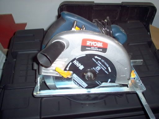
The other day while strolling through Game in Menlyn I found a little special on some of their tools. A little stand drill for a mere R350.
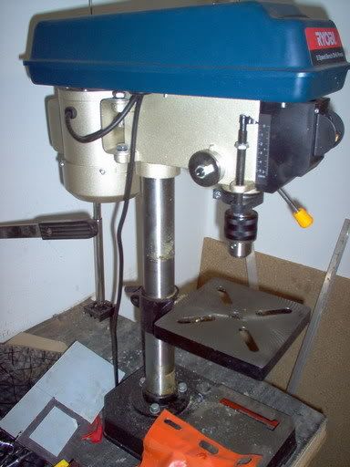
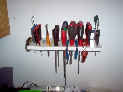
And then my parents-in-law was so kind to provide me with another little luxury:
So then I just had to make something and well this was first.
I then made this with the drill
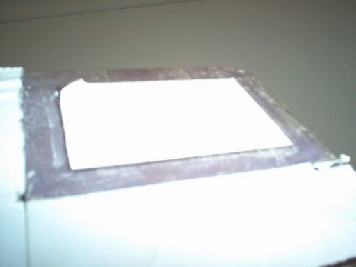
Basically if go look at some previous pictures, you'll see a LCD screen on the front panel. The perspex covering that was not to size and I decided to remake that part. I still need to cut it out and fit it to the case though.
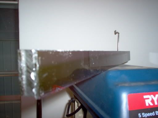
I went to Maizeys the other day and bought a few pieces of plexi and perspex. All six measuring 500mm x 30mm. Oh and some perspex glue (Dont inhale that stuff, you'll start talking to the little pink elephant next to your pointy 3rd ear...) So I glued these pieces in stages (the pointy 3rd ear thing was upsetting) And this how it turned out
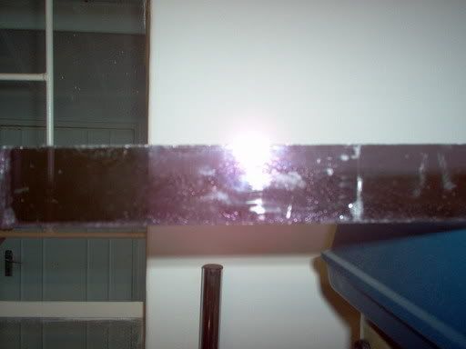
Colouring

I started to polish the thing just to see whet it would look like
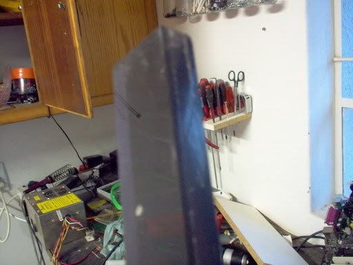
Now I know your asking "what the hell is it???" It is going to be the feet of my case. The idea actually came to me form one of our fellow modders, though he doesn't know it. Thanks Skidd. Yes they are going to be skidds. As in like skidds on some helicopters but on a computer with little lights and stuff.
Posted: 05 Sep 2007, 19:44
by Skidd
Looking awesome man!
Posted: 22 Sep 2007, 22:20
by Samaya
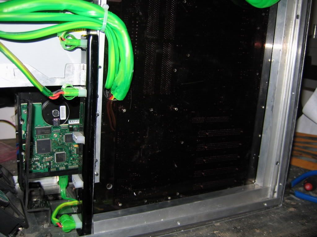
I was busy on the computer the other day and thought that my PC was a bit loud. As in the fans spinning at full speed the whole time is kinda annoying. So yesterday I went to Communica, bought a bunch of electronic components and made my own little fan controller. Ok first off its NOT fancy but it is automatic (I do not turn knobs for stupid fans). As the temperature rises the fan speed increases and vice versa.
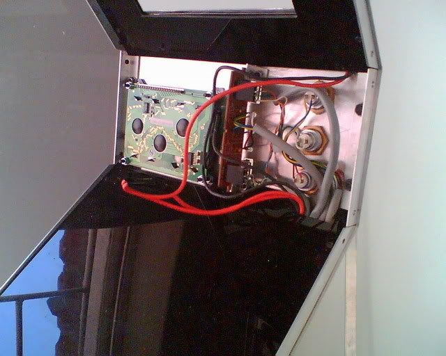
First off. I used Vero Board for the PCB.
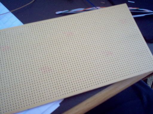
I soldered in the opamp I was going to use, the driving transistors and resistors. I did the thermistor last as I had it on a wire extension. This whole business runs off 12V.
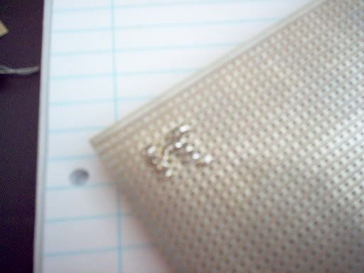
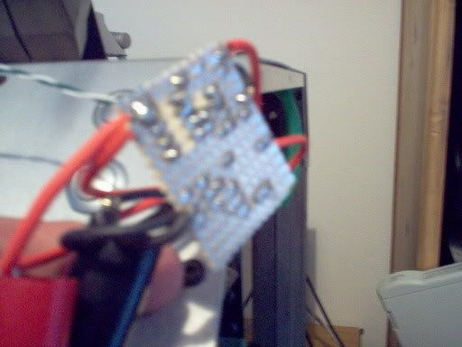
You will notice my multi meter's test leads. I checked the voltage across the fans when I "simulated" a temperature rise in my machine. Voltage rised when I held onto the thermistor. So it is working perfectly fine.
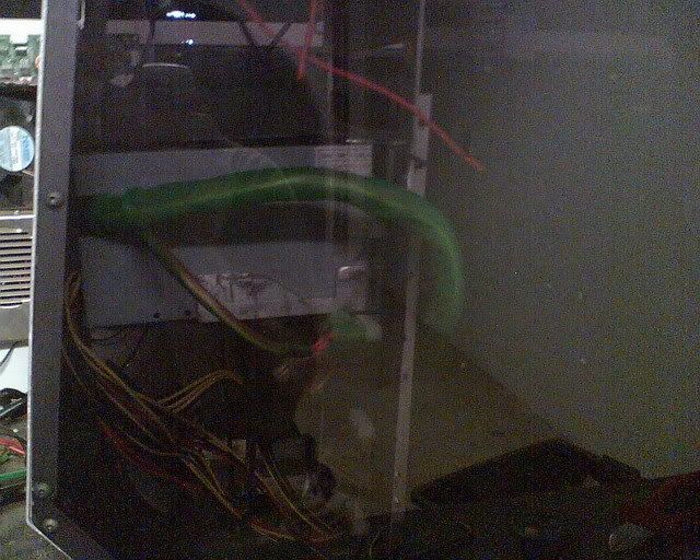
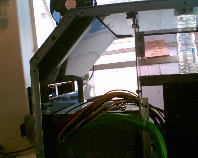
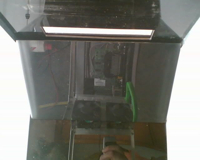
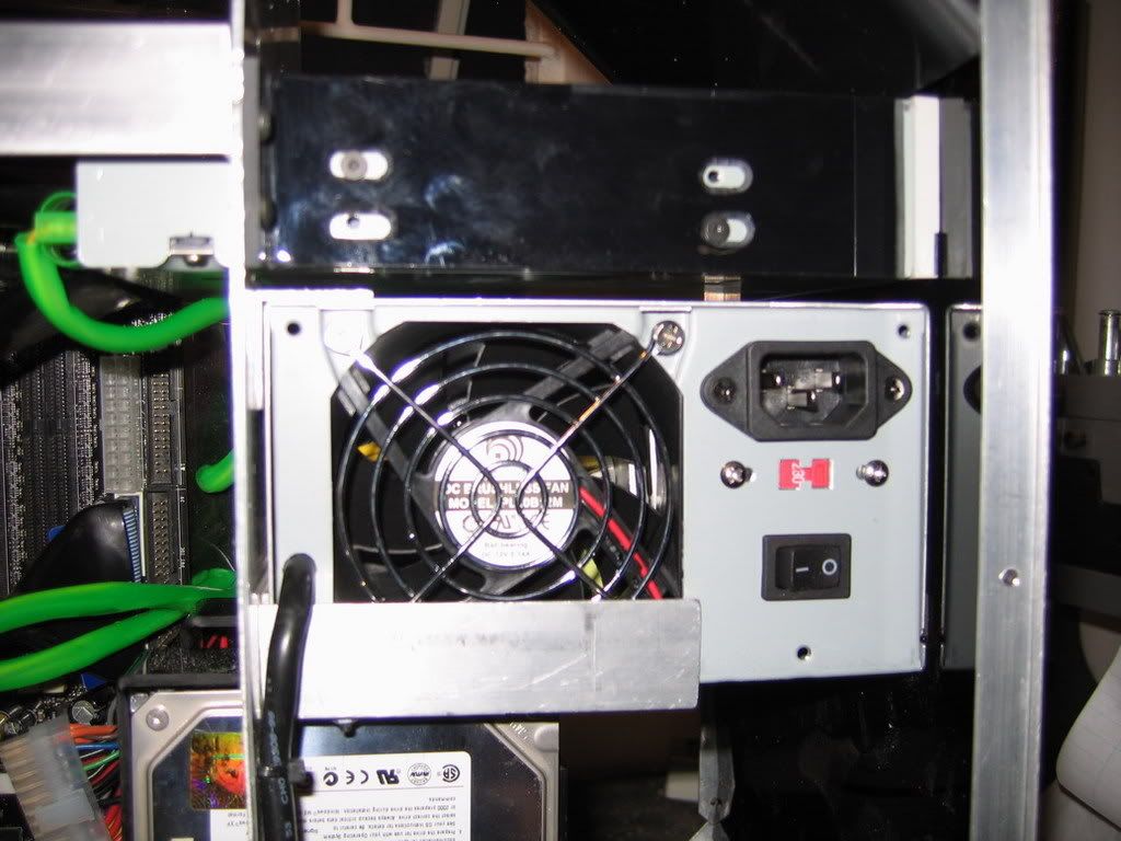
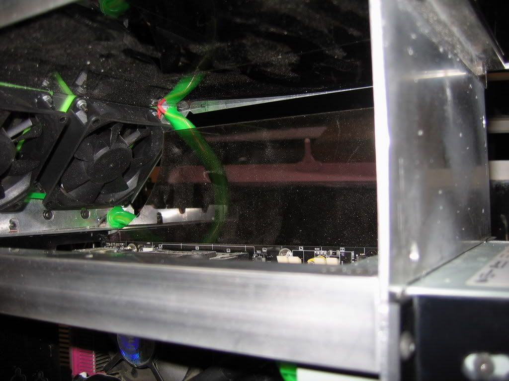
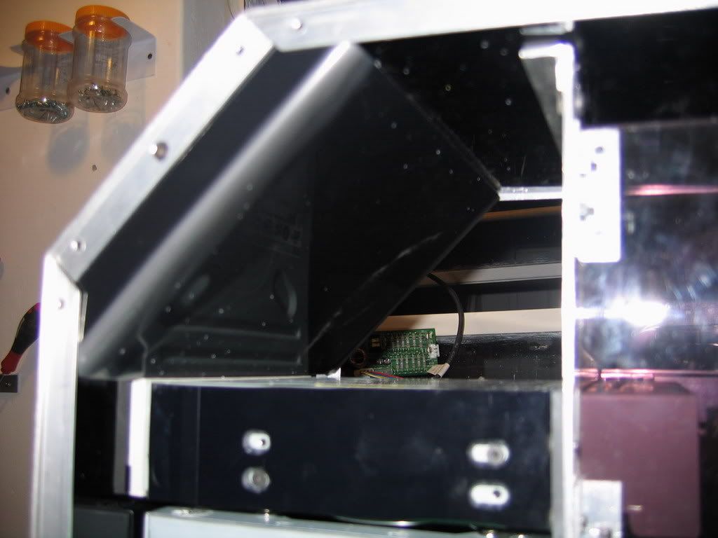
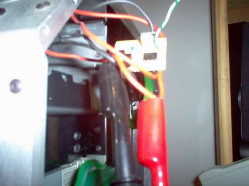
This area should be the warmest place in my box as this is one area where there is the least amount of ventilation. There are also no critical components there.
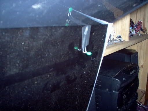
And then finally box closed. My temps are stable at 38C (MB) and 44C (CPU). My ambient temperature is about 29C.
On Monday and maybe tomorrow I'll make another gadget, OTC asked for this one and I finally have the time to make it...
Posted: 22 Sep 2007, 22:32
by I34z1k
Dude, like I said, I LOVE YOUR CASE
Posted: 22 Sep 2007, 22:46
by DAE_JA_VOO
Samaya for president!
Posted: 22 Sep 2007, 22:48
by I34z1k
Lol. He's one of the few I remember from my early forum days

Posted: 22 Sep 2007, 22:55
by DAE_JA_VOO
I34z1k wrote:Lol. He's one of the few I remember from my early forum days
Well i'm still
IN my "early forum days", so i remember everyone
Posted: 22 Sep 2007, 23:01
by I34z1k
Lol 2 years is good my son
Posted: 23 Sep 2007, 09:48
by Samaya
Thanks guys
It seems my day has been planned for me already by a shopaholic wife and beautiful baby girl... I might have some free time later this afternoon to work on the next gadget
Posted: 02 Oct 2007, 07:34
by Lithe_Joint
Very Cool. (No pun intended). Could you use the same circuit to control LED's?
Posted: 02 Oct 2007, 09:21
by Samaya
In theory yes. I'll post the circuit tonight if you want. I just don't have it with me at the moment.
It is just a voltage follower op-amp circuit basically, that has a NTC resistor for input. Then the actual driving of the circuit is done by 3 transistors, BC639's. The Op-amp is only there so the NTC has the smallest amount of load (current flowing through it) and the Op-amp can drive the transistors.
If you would like to drive a LED, you would need to place a resistor before the LED which you can replace the FANS with. So you could in fact make a bar graph temperature display with it as well.